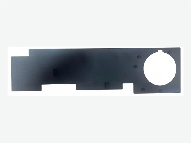
A busbar insulator specification that only lists dielectric strength in kV/mm is incomplete. The released drawing must also define working voltage, transient voltage, creepage, clearance, edge coverage, and post-aging acceptance. This article explains how to build that specification so the converted part survives both normal operation and validation testing.
Start with the Insulation Coordination Set, Not the Material Datasheet
Dielectric strength is a material property measured under specific laboratory conditions—usually a short-duration AC or DC ramp on a flat, clean sample. It does not tell you whether a formed busbar insulator will survive 800 V DC in a battery pack with contamination, humidity, and mechanical stress. The specification must begin with the insulation coordination set: working voltage, transient overvoltage, pollution degree, and the required creepage and clearance distances.
IEC 60664-1 defines creepage as the shortest path along an insulating surface and clearance as the shortest path through air. For an 800 V DC working voltage at pollution degree 2 with a material group IIIa surface, the standard tables call for roughly 8.0 mm of creepage. Clearance is typically smaller because air does not track contamination the way a surface can. These are reference points, not substitutes for a full calculation that includes altitude, insulation type, and the specific voltage in your design.1
A practical approach is to first determine the minimum creepage and clearance from the applicable standard, then design the busbar insulator geometry to maintain those distances across all bends, folds, and fastener locations. Only after the geometry is fixed should you select a material grade and thickness that provides the required dielectric withstand with margin.
- Working voltage: the continuous DC or AC voltage across the insulator in normal operation.
- Transient voltage: the expected overvoltage from switching, load dump, or other events.
- Pollution degree: the expected contamination level on the surface, which drives creepage requirements.
- Material group: the comparative tracking index (CTI) class of the insulation surface.
Dielectric Strength Is a Screening Value, Not a Rating
A PET film datasheet may list dielectric strength from 154 to 350 kV/mm, but that range depends on grade, thickness, test method, and conditioning. A 0.025 mm film with a 200 kV/mm rating would theoretically withstand 5 kV, but that calculation ignores edge effects, pinholes, adhesive layers, and aging. Never use the raw kV/mm value as a working-voltage rating.2
For a converted busbar insulator, the relevant question is whether the finished part—after die cutting, folding, and adhesive lamination—passes a hipot test at the specified voltage for the specified duration. The test voltage should be derived from the working voltage and the required insulation class, not from the material datasheet. For example, a 1,000 V DC working voltage might require a 2,500 V DC hipot test for one minute, but the exact value depends on the standard and the safety margin.
When comparing PET and polyimide, consider more than dielectric strength. Polyimide offers higher temperature capability and better dimensional stability, but it is more expensive and may require special handling. PET is lower cost and easier to convert, but its dielectric strength drops more quickly with temperature and humidity. The choice depends on the maximum operating temperature, the required mechanical robustness, and the cost target.
- PET thickness range: 0.012–0.500 mm (available screening range).
- Polyimide thickness range: 0.0127–0.125 mm (available screening range).
- Dielectric strength screening range: 154–350 kV/mm for selected film examples; grade, thickness, and method required.
- Always specify the hipot test voltage and duration on the drawing, not just the material property.
Edge Coverage and Creepage Extension: The Overlooked Failure Path
A busbar insulator that covers the flat surface but leaves the edges exposed creates a creepage path along the cut edge. The edge is often rougher and more contaminated than the film surface, reducing the effective creepage distance. The specification must define how far the insulation extends beyond the busbar edge—typically 2–5 mm, depending on voltage and pollution degree—and whether the edge is folded, sealed, or left open.
For high-voltage busbars, a common approach is to use a formed insulator that wraps around the busbar edges, increasing the creepage path without adding a separate edge seal. This requires precise die cutting and folding, which is where a converter with experience in battery insulation can add value. The drawing should show the exact fold geometry, adhesive placement, and any overlap or gap at the seam.
Fastener holes and weld zones are another edge coverage concern. A punched hole creates a new edge with reduced creepage distance to the busbar. The specification should require a minimum distance from the hole edge to the busbar surface, or specify an insulating grommet or collar. Similarly, weld zones may need additional insulation because the heat-affected area can degrade the film.
- Define edge extension beyond the busbar: 2–5 mm typical, but voltage-dependent.
- Specify fold geometry and adhesive placement for wrapped insulators.
- Set minimum distance from fastener holes to busbar surface.
- Consider additional insulation at weld zones due to heat degradation.
Post-Aging Acceptance: The Specification That Catches Latent Failures
A busbar insulator that passes hipot on day one may fail after thermal cycling, humidity exposure, or mechanical vibration. The specification must include post-aging acceptance criteria. Common aging conditions include thermal cycling from -40°C to +85°C or +105°C, damp heat at 85°C/85% RH, and mechanical vibration per LV 214 or USCAR-2 profiles. After aging, the part must still pass the hipot test at the specified voltage.
The post-aging test should be defined in the drawing or a separate validation plan. For example: after 500 thermal cycles from -40°C to +85°C, the insulation resistance must be above 100 MΩ at 500 V DC, and the part must withstand 2,500 V DC for 60 seconds without breakdown. The exact values depend on the application, but the principle is to test the part in a condition that represents end-of-life, not just initial assembly.
When specifying post-aging acceptance, consider the failure mode you are trying to catch. A gradual increase in leakage current may indicate moisture ingress or contamination, while a sudden breakdown suggests a mechanical defect or localized degradation. The hipot test should be able to distinguish these, either through waveform capture or by measuring leakage current at multiple voltage steps.3
- Thermal cycling: -40°C to +85°C or +105°C, 500–1,000 cycles typical.
- Damp heat: 85°C/85% RH for 1,000 hours common for automotive.
- Vibration: LV 214 or USCAR-2 profiles, with hipot test after exposure.
- Acceptance: insulation resistance above 100 MΩ at 500 V DC, hipot at 2,500 V DC for 60 seconds (example values).
Material Selection: PET vs. Polyimide vs. Mica
PET film is the default choice for busbar insulation in 400 V systems where temperatures stay below 105°C. It is low cost, easy to die cut, and available in a wide range of thicknesses. Polyimide is preferred for 800 V systems or locations near high-temperature components, because it maintains dielectric strength and mechanical integrity above 200°C. Mica is used for rigid busbar supports or fire barriers, but it is brittle and requires different converting processes.
The selection matrix below summarizes the key trade-offs. Note that these are general engineering guidelines, not absolute rules. The final choice depends on the specific voltage, temperature, mechanical, and cost requirements of your application.
- PET: lowest cost, good dielectric strength up to 105°C, easy to convert.
- Polyimide: highest temperature capability, excellent dielectric strength, higher cost.
- Mica: rigid, high-temperature, fire-resistant, but brittle and requires special handling.
- FR-PC: flame-retardant polycarbonate, good impact resistance, moderate temperature capability.
Drawing Inputs That Make the RFQ Unambiguous
A clear drawing is the single most important factor in getting a busbar insulator that meets your specification. The drawing should include the following: busbar dimensions and material, working voltage and transient voltage, required creepage and clearance distances, insulation material and thickness, edge extension and fold geometry, adhesive type and placement, fastener hole locations and sizes, and the post-aging acceptance criteria.
For a converted part, also specify the tolerances on critical dimensions, especially the edge extension and hole positions. A tolerance of ±0.5 mm on edge extension may be acceptable for a 400 V system, but an 800 V system may require ±0.25 mm or better. The drawing should also state whether the part is supplied as a flat sheet, a formed shape, or a pre-folded assembly.
Finally, include the validation plan as a separate document or an appendix to the drawing. The plan should define the test samples, conditioning sequence, test voltages, durations, and acceptance limits. This ensures that the supplier and the customer are testing the same thing.
- Busbar dimensions and material.
- Working voltage and transient voltage.
- Required creepage and clearance distances.
- Insulation material, thickness, and grade.
- Edge extension and fold geometry.
- Adhesive type and placement.
- Fastener hole locations and tolerances.
- Post-aging acceptance criteria and test plan.
Decision Matrix: Choosing the Right Insulation Approach
The following matrix is a VOLTFEND engineering synthesis to help you decide between a flat sheet, a wrapped insulator, or a rigid mica support. It is not a substitute for a full design review, but it provides a starting point for discussion.
- Flat sheet: lowest cost, suitable for low voltage (<60 V) or where creepage is not critical.
- Wrapped insulator: moderate cost, increases creepage path, suitable for 400–800 V busbars.
- Rigid mica support: highest cost, provides mechanical support and fire resistance, suitable for high-temperature or fire-prone areas.
- Combination: use flat sheet for general coverage and wrapped insulator at high-voltage joints or terminations.
PROJECT CHECKLIST
Inputs to bring into the next review
- 01Cell format and chemistry (e.g., prismatic LFP, cylindrical NMC) to understand thermal and electrical environment.
- 02Busbar dimensions, material, and surface finish (copper, aluminum, plated).
- 03Working voltage and maximum transient voltage.
- 04Required creepage and clearance distances per applicable standard (IEC 60664-1, ISO 21498, LV 123).
- 05Pollution degree and material group (CTI) for the application.
- 06Insulation material preference (PET, polyimide, mica, FR-PC) and thickness.
- 07Edge extension and fold geometry requirements.
- 08Adhesive type and placement, if any.
- 09Fastener hole locations, sizes, and tolerances.
- 10Post-aging test conditions (thermal cycling, damp heat, vibration) and acceptance limits.
- 11Target volume and any special packaging or traceability requirements.
ENGINEERING FAQ
Questions teams commonly ask
What is the difference between dielectric strength and working voltage?
Dielectric strength is a material property measured in kV/mm under specific lab conditions. Working voltage is the continuous voltage the insulator must withstand in the application. The working voltage, along with transient overvoltages and pollution degree, determines the required creepage and clearance distances, which then drive the material thickness and geometry.
How do I calculate creepage and clearance for an 800 V DC busbar?
Use IEC 60664-1 or ISO 21498 tables. For 800 V DC at pollution degree 2 with material group IIIa, creepage is roughly 8.0 mm and clearance is smaller. These are reference values; you must adjust for altitude, insulation type, and specific voltage. A qualified engineer should perform the final calculation.1, 4
Can I use PET film for an 800 V busbar insulator?
PET can be used if the temperature stays below 105°C and the creepage/clearance requirements are met with sufficient edge extension. However, polyimide is often preferred for 800 V systems because it maintains dielectric strength at higher temperatures and has better dimensional stability. The choice depends on the specific thermal and mechanical environment.
What post-aging tests should I specify for a busbar insulator?
Typical tests include thermal cycling (-40°C to +85°C or +105°C, 500–1,000 cycles), damp heat (85°C/85% RH, 1,000 hours), and vibration (LV 214 or USCAR-2). After aging, the part must pass a hipot test at the specified voltage and maintain insulation resistance above a defined threshold, such as 100 MΩ at 500 V DC.
How does VOLTFEND help with busbar insulation specification?
VOLTFEND is a direct manufacturer of drawing-specific converted battery insulation components. We can slit, laminate, die cut, laser cut, inspect, and pack PET, polyimide, and other film insulators to your drawing. We provide samples within 7 days after drawing and material confirmation, with no MOQ in principle. Send your busbar dimensions, voltage requirements, and post-aging targets for a feasibility review.2
SOURCES
Evidence used in this brief
- 1EV Battery Management System PCB Design: High Voltage Isolation and Layout Rules
nextpcb.com · Accessed October 13, 2026
- 2Custom Battery Film Insulation Parts engineering data and screening boundaries
VOLTFEND Engineering · Accessed October 13, 2026
- 3Insulation Failure “Visualization” for More Efficient Battery Hipot Testing | HIOKI
hioki.com · Accessed October 13, 2026
- 4Creepage and Clearance Calculator - Battery Design
batterydesign.net · Published June 25, 2026 · Accessed October 13, 2026