Application engineering brief
Custom Busbar Insulation Components
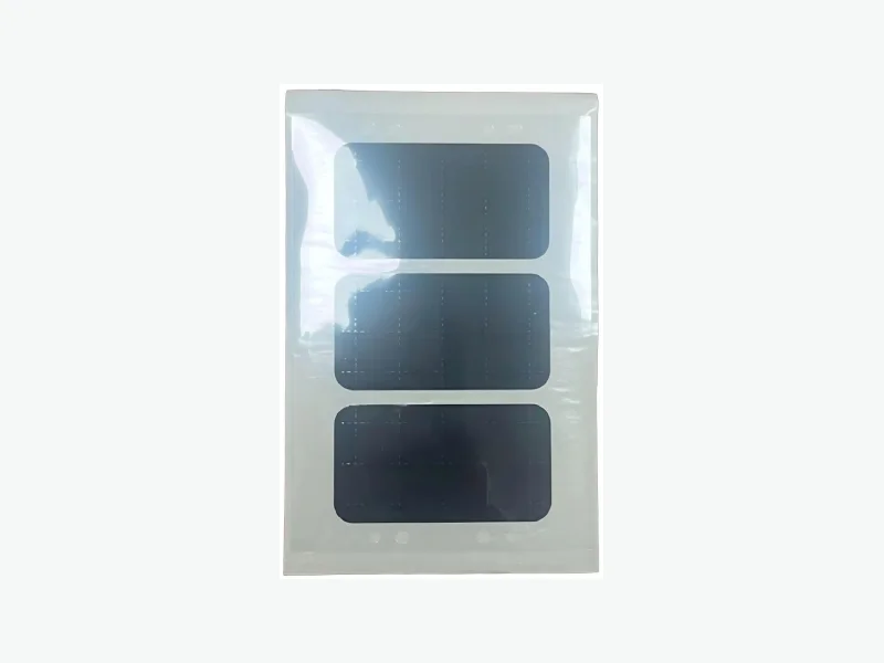
Die-cut, folded and laminated insulation around busbar geometry, terminals and high-voltage interfaces.
The engineering problem
Start with the installed interface.
Busbar corners, weld zones, fasteners and dimensional variation can defeat a flat material assumption and concentrate electrical or mechanical stress.
We translate the conductor and assembly drawing into coverage, fold, adhesive, liner and delivery-format decisions.
Position and function
Where this component works—and what it must do
- Busbar face
- Terminal and weld-adjacent area
- Fastener interface
- Module interconnect
- Pack distribution unit
- Conductor coverage
- Edge and corner isolation
- Assembly location
- Optional rigid support or high-temperature layer
Selection logic
Decision data customers and engineers expect
| Decision dimension | What must be defined |
|---|---|
| Coverage | Mark keep-outs, weld zones and exposed-edge limits. |
| Forming | Define folds, bend radius and springback. |
| Bond | Match adhesive to substrate, temperature and assembly sequence. |
| Inspection | Choose critical dimensions and visual criteria. |
Data required
Send these inputs for a useful first review
- Busbar and assembly drawing
- Voltage and electrical clearance
- Weld and fastener keep-outs
- Temperature and substrate
- Delivery format and volume
Continue the evaluation
Related engineering pathways
Frequently asked questions
Clear answers before sampling
Can die-cut film cover a three-dimensional busbar?
Folds or formed sheet may work, but radius, strain and assembly sequence must be reviewed.
Can adhesive be added selectively?
Yes, depending on geometry and converting feasibility. The adhesive pattern and liner become controlled drawing features.
Is mica always required?
No. Material selection depends on temperature, rigidity, dielectric, flame and integration demands.
Drawing-led response