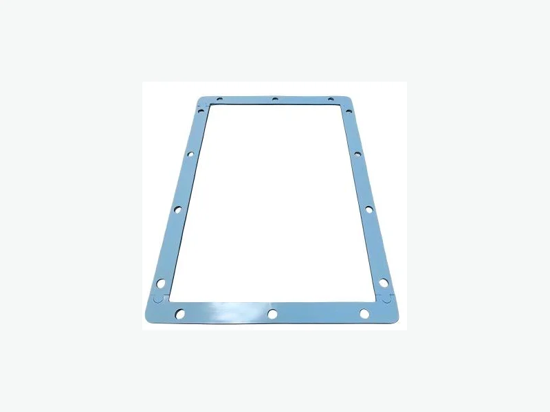
Compression pad aging validation answers one question: will the pad keep the cell stack inside its allowable pressure window from beginning of life to end of life? The answer depends on two coupled material responses—stress relaxation and compression set—measured under the module's actual temperature, strain, and time conditions. A pad that looks acceptable at room temperature can lose too much force after 1,000 hours at 60 °C, or take a permanent set that opens a gap and lets cells breathe. This article gives battery module mechanical engineers a practical validation framework: what to measure, how to condition specimens, how to set acceptance limits, and what drawing inputs make a supplier review useful.
Why Compression Pad Aging Is a Module-Level Decision
A compression pad is not a standalone spring. It works inside a constrained stack where the cell, end plates, frame, and pad all share displacement. As the cell grows with state of charge and calendar aging, the pad absorbs part of that growth and maintains a controlled force on the cell face. If the pad relaxes too much, the stack loses preload and the cell can delaminate internally. If the pad takes too much compression set, the installed thickness decreases permanently and the force window shifts downward. Both failure modes are time- and temperature-dependent, so they cannot be screened with a single room-temperature compression curve.
The workable pressure window depends on cell chemistry, format, and frame stiffness, so module builders validate compression against the specific cell rather than copying a value from another design. For pouch cells, a typical optimal range is around 20 to 40 kPa, but that is a starting point, not a universal target. Prismatic cells with rigid cans have different force limits and growth behavior. The pad must be selected so that the force at beginning of life, after initial relaxation, and at end of life all stay inside the cell supplier's allowed range.1, 2
- Cell format and chemistry set the allowable force window
- Module frame stiffness changes how much cell growth reaches the pad
- Aging validation must cover the full service temperature envelope
Stress Relaxation vs. Compression Set: Two Different Aging Mechanisms
Stress relaxation is the loss of force when the pad is held at a constant strain. In a module, the pad is compressed to a target thickness and then the stack is locked. Over time, the pad's internal polymer network rearranges, and the force it exerts decays. Compression set is the permanent deformation that remains after the load is removed. A pad with high compression set does not recover its original thickness, so the next time the module is assembled or the cell contracts, the pad is thinner and exerts less force. Both mechanisms are accelerated by temperature and are material-grade specific.
Silicone rubber foams are often chosen for compression pads because the silicon–oxygen backbone provides good resistance to thermal aging and compression set compared with many organic elastomers. However, that does not mean all silicone grades behave the same. Filler type, foam density, cell structure, and cure chemistry all change the relaxation and set behavior. A grade that shows 5% force loss after 1,000 hours at 25 °C may show 25% loss at 60 °C. Validation must therefore use the actual grade and the actual service temperature, not a generic material family claim.3
- Stress relaxation: force decay at constant strain
- Compression set: permanent thickness loss after unloading
- Both are temperature-accelerated and grade-specific
Defining the Aging Test Conditions
A useful aging validation plan starts with three inputs: the installed strain, the maximum continuous service temperature, and the required lifetime. Installed strain is the pad thickness reduction at assembly, typically 20–40% for silicone foam pads. The maximum continuous temperature is the highest temperature the pad sees for a meaningful fraction of its life, not a short-term peak. For an EV module, this might be 45–60 °C near the cells; for an ESS module in a hot climate, it could be higher. The required lifetime is usually the vehicle or system warranty period, often 10–15 years, but accelerated testing must compress that into weeks or months.
Accelerated aging uses elevated temperature to speed up the polymer relaxation processes. A common approach is to age specimens at two or three temperatures above the service maximum, for example 70 °C, 85 °C, and 100 °C, and then use time–temperature superposition or an Arrhenius model to predict long-term behavior. However, the acceleration model must be validated for the specific material. Silicone foams can show non-Arrhenius behavior if the aging mechanism changes, for example from physical relaxation to oxidative crosslinking. A practical screening plan often includes a 1,000-hour test at the maximum service temperature plus a shorter high-temperature test to check for unexpected degradation.
- Installed strain: typically 20–40% for silicone foam pads
- Test temperature: maximum continuous service temperature, not peak
- Duration: 1,000 hours minimum for screening, longer for qualification
Test Methods and What to Measure
Stress relaxation is measured by compressing the pad to the target strain between parallel plates and recording the force over time. The test can be run in a controlled-environment chamber with a load cell. The key output is the force retention percentage: force at time t divided by initial force. For a module pad, the relevant time points are often 24 hours, 168 hours, 500 hours, and 1,000 hours. Compression set is measured per ASTM D395 Method B (constant deflection) or ISO 815. The specimen is compressed to a defined strain, aged at temperature for a set time, then released and allowed to recover for 30 minutes at room temperature. The set is the percentage of original thickness not recovered.
Compression force deflection (CFD) testing, as described in ASTM D575, measures the stress required to compress a foam specimen to defined strain levels. This is useful for generating the pressure–strain curve of a candidate pad, but it is not an aging test by itself. The aging test must hold the strain constant and track force decay. For a complete validation, measure both stress relaxation and compression set on the same grade, because a pad can have acceptable relaxation but unacceptable set, or vice versa.4
- Stress relaxation: force retention at 24 h, 168 h, 500 h, 1,000 h
- Compression set: ASTM D395 Method B or ISO 815
- CFD (ASTM D575) for pressure–strain curve, not aging
Setting Acceptance Limits from the Cell Force Window
Acceptance limits must be derived from the cell supplier's allowable pressure range, not from a generic material target. Start with the cell's minimum and maximum recommended face pressure at beginning of life and end of life. Then calculate the pad's force at the installed strain, after expected stress relaxation, and after expected compression set. The pad passes if the predicted force at every life point stays inside the cell's window. For example, if the cell allows 15–50 kPa and the pad starts at 35 kPa, a 30% relaxation would drop it to 24.5 kPa, still inside the window. But if the pad also takes 10% compression set, the installed strain decreases and the force may drop further. The combined effect must be evaluated.
A practical acceptance criterion for screening is often: force retention ≥ 70% after 1,000 hours at the maximum service temperature, and compression set ≤ 10% after the same aging. These are not universal limits; they are starting points that must be adjusted based on the cell window and module tolerance. A pad with a wider initial force margin can tolerate more relaxation. A pad with a narrow window needs tighter limits. The key is to write the acceptance limits into the drawing or specification before qualifying the grade, so that the supplier and the module engineer are testing against the same target.
- Derive limits from cell supplier's allowable pressure range
- Evaluate combined effect of relaxation and set
- Write acceptance limits into the drawing or specification
VOLTFEND Drawing-Input Framework for Aging Validation
When VOLTFEND reviews a compression pad drawing for aging validation, the following inputs make the review actionable. First, the cell format and chemistry, because they set the force window and growth profile. Second, the installed strain or target thickness and the module gap tolerance. Third, the maximum continuous service temperature and any short-term peak temperatures. Fourth, the required lifetime and the acceleration model you plan to use. Fifth, the acceptance limits for force retention and compression set. Sixth, the pad's active support area and any cutouts, because local stress concentrations can change the effective strain. With these inputs, VOLTFEND can recommend candidate silicone foam grades, provide representative pressure–strain curves, and discuss a screening test plan.
VOLTFEND supplies drawing-specific converted silicone compression pads and cell expansion pads. The engineering data available includes pressure–strain curves, gap tolerance, stress relaxation, compression set, and liner and placement decisions. Representative screening ranges for silicone compression pads include thickness from 1.0 to 3.0 mm, density from 112 to 400 kg/m³, and pressure at 25% strain from 10.3 to 83 kPa. These are candidate-family ranges, not universal values. The exact grade, construction, and supplier evidence control the released part. Complete battery performance must be validated in the customer's assembly.5, 6
- Cell format, chemistry, and force window
- Installed strain and gap tolerance
- Service temperature and lifetime
- Acceptance limits for relaxation and set
- Active support area and cutouts
Validation Protocol: A Step-by-Step Sequence
Step 1: Confirm the cell supplier's allowable pressure range at beginning and end of life. Step 2: Select two or three candidate pad grades with different densities or pressure–strain curves. Step 3: Measure the pressure–strain curve for each grade at room temperature and at the maximum service temperature. Step 4: Run stress relaxation at the installed strain for 1,000 hours at the maximum service temperature. Step 5: Run compression set per ASTM D395 Method B at the same temperature and duration. Step 6: Calculate the predicted force at end of life for each grade, including the effect of compression set on installed strain. Step 7: Compare the predicted force to the cell's allowable window. Step 8: Select the grade that stays inside the window with margin, and document the acceptance limits in the drawing.
This protocol is a screening tool, not a substitute for full module validation. The pad's behavior in the real module depends on the frame stiffness, cell growth profile, thermal gradients, and assembly tolerances. After selecting a grade, run a module-level test with instrumented cells or pressure-sensitive film to confirm the actual force distribution. The pad supplier can provide material-level data, but the module engineer owns the system-level validation.
- Confirm cell force window
- Screen candidate grades
- Run relaxation and set tests
- Predict end-of-life force
- Validate at module level
PROJECT CHECKLIST
Inputs to bring into the next review
- 01Cell format (pouch, prismatic, cylindrical) and chemistry
- 02Cell supplier's allowable pressure range at beginning and end of life
- 03Installed strain or target pad thickness
- 04Module gap tolerance and frame stiffness
- 05Maximum continuous service temperature and peak temperature
- 06Required lifetime and acceleration model
- 07Acceptance limits for force retention and compression set
- 08Pad active support area and cutout geometry
- 09Drawing or specification with defined test conditions
- 10Volume and sample requirements for supplier review
ENGINEERING FAQ
Questions teams commonly ask
What is the difference between stress relaxation and compression set for a battery compression pad?
Stress relaxation is the loss of force when the pad is held at a constant strain over time. Compression set is the permanent thickness loss after the load is removed. Both reduce the pad's ability to maintain pressure on the cell, but they act through different mechanisms and must be measured separately.
What temperature should I use for compression pad aging tests?
Use the maximum continuous service temperature the pad will see for a meaningful fraction of its life, not a short-term peak. For EV modules this is often 45–60 °C; for ESS in hot climates it may be higher. Accelerated tests at higher temperatures can be used, but the acceleration model must be validated for the specific material.
How long should a compression pad aging test run?
A practical screening test runs for 1,000 hours at the maximum service temperature. For qualification, longer durations or multi-temperature testing with time–temperature superposition may be needed to predict 10–15 year behavior. The duration should be tied to the required lifetime and the acceleration model.
What are typical acceptance limits for compression pad aging?
A common starting point is force retention ≥ 70% and compression set ≤ 10% after 1,000 hours at the maximum service temperature. These are not universal; they must be adjusted based on the cell's allowable pressure window and the module's tolerance. A pad with a wider initial force margin can tolerate more relaxation.
Can VOLTFEND provide compression pad aging data?
VOLTFEND can provide representative pressure–strain curves and discuss stress relaxation and compression set for candidate silicone foam grades. The exact grade, construction, and supplier evidence control the released part. Complete battery performance must be validated in the customer's assembly. Samples are available within 7 days after drawing and material confirmation.5
SOURCES
Evidence used in this brief
- 1The Role of Compression Pads in EV Batteries
azom.com · Published March 26, 2026 · Accessed October 18, 2026
- 2Pouch Cell Battery Module: Swelling, Compression, Cooling
trumonytechs.com · Published September 30, 2026 · Accessed October 18, 2026
- 3How Temperature Affects Heat-Resistant Silicone Rubber
elastostar.com · Accessed October 18, 2026
- 4Compression Deflection Testing: ASTM D575, CFD and IFD
infinitalab.com · Accessed October 18, 2026
- 5Silicone Battery Compression Pads engineering data and screening boundaries
VOLTFEND Engineering · Accessed October 18, 2026
- 6Battery Cell Expansion Pads engineering data and screening boundaries
VOLTFEND Engineering · Accessed October 18, 2026