Application engineering brief
Battery Cell Compression Management
Use cell expansion, tolerance and target pressure to define the pad’s working strain across battery life.
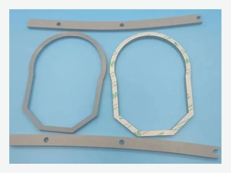
The engineering problem
Start with the installed interface.
A pad that fits at assembly can still produce too little or too much force after swelling, thermal cycling and long-term stress relaxation.
We convert the module’s dimensional and force requirements into a candidate pad thickness, grade, outline and validation matrix.
Position and function
Where this component works—and what it must do
- Between prismatic cells
- Pouch-cell face
- Cell-to-end-plate interface
- Module side restraint
- Tolerance absorption
- Pressure distribution
- Expansion accommodation
- Vibration and handling support
Selection logic
Decision data customers and engineers expect
| Decision dimension | What must be defined |
|---|---|
| BOL | Calculate installed strain and pressure at beginning of life. |
| EOL | Include cell expansion, pad set and stress relaxation. |
| Uniformity | Review pressure distribution around openings and edges. |
| Process | Define liner removal, datum and placement control. |
Data required
Send these inputs for a useful first review
- Cell face and stack count
- Gap min/nominal/max
- Expansion range
- Target pressure window
- Aging condition and drawing
Continue the evaluation
Related engineering pathways
Frequently asked questions
Clear answers before sampling
Can density select the pad?
Density is not a pressure–strain curve and cannot replace force data at the intended compression.
Should pressure stay constant?
The acceptable change is a cell and module design input; the pad must be evaluated across the defined life window.
Can adhesive affect compression?
Yes. Adhesive, carrier and liner add thickness and can influence constraint and assembly behavior.
Drawing-led response