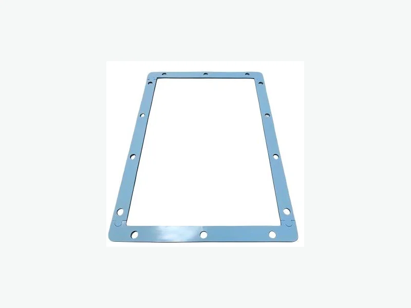
A battery cell compression pad pressure window is the range of face pressure that keeps a prismatic or pouch cell mechanically supported without over-constraining it from beginning of life to end of life. The window is not a single number; it is a corridor bounded by minimum pressure for layer contact and maximum pressure for cell health, evaluated across the module's gap tolerance and the cell's irreversible growth. Set the window from pressure-strain data for the exact pad grade, then verify it with aging and relaxation tests in the real assembly.
Start with the cell's pressure limits, not the pad's hardness
The first input is the cell manufacturer's allowable face pressure range. Prismatic cells often specify a minimum pressure to maintain internal layer contact and a maximum pressure to avoid separator compression or lithium plating. Pouch cells are similar but rely entirely on the module for support, so the module frame and compression system must supply the entire window. The pad is only one element in that system; its job is to convert the available gap into a controlled force.
Do not select a pad by Shore hardness or density. Two pads with the same hardness can have very different pressure-strain curves because of foam structure, skin layers, and filler. The correct selection input is the pressure-strain curve for the exact grade at the installed thickness and temperature. VOLTFEND's silicone compression pad family shows a representative screening range of 10.3 to 83 kPa at 25% strain, but that range spans multiple grades and is not a universal design value. The released part must be specified from the grade-specific curve.1
- Obtain the cell manufacturer's minimum and maximum face pressure limits.
- Request pressure-strain curves for candidate pad grades at the installed thickness.
- Ignore hardness and density as primary selection criteria.
Build the pressure window from gap tolerance and cell growth
The installed pad thickness is set by the module's nominal gap minus the pad's free thickness. The gap has a tolerance from frame machining, cell thickness variation, and stack-up. The cell also grows with state of charge and aging. The pad must operate within its useful strain range across the entire gap tolerance and the full cell growth envelope. A common approach is to define the minimum gap as the worst-case stack-up at beginning of life and the maximum gap as the worst-case stack-up at end of life after irreversible swelling.
For a pouch cell module, the workable compression window depends on cell chemistry, format, and frame stiffness, so module builders validate compression against the specific cell rather than copying a value from another design. The same principle applies to prismatic modules: the pad's pressure-strain curve must be overlaid with the cell's growth curve to see if the resulting pressure stays inside the cell's allowable range. If the pressure at minimum gap exceeds the cell's maximum, the pad is too stiff or too thick. If the pressure at maximum gap falls below the cell's minimum, the pad is too soft or too thin.2
- Define minimum and maximum installed gap from tolerance analysis.
- Overlay cell growth curve on pad pressure-strain curve.
- Check pressure at both gap extremes against cell limits.
Account for stress relaxation and compression set over life
A compression pad loses force over time due to stress relaxation, and it may not fully recover after long-term compression due to compression set. Both effects reduce the pad's ability to maintain the minimum pressure at end of life. The amount of relaxation depends on the material, temperature, initial strain, and time. Silicone foams generally have lower compression set than many polyurethane foams, but the exact grade must be tested under the module's temperature profile.
Stress relaxation is not a single number; it is a curve of force versus time at constant strain. A pad that relaxes 20% in the first 100 hours may relax only 5% more over the next 10,000 hours. The design must use the relaxation curve at the expected maximum temperature, not a room-temperature value. VOLTFEND's engineering data for silicone compression pads explicitly lists stress relaxation and compression set as required decision inputs, meaning the exact grade's evidence must be reviewed before release.1
- Request stress relaxation curves at maximum operating temperature.
- Include compression set in end-of-life pressure prediction.
- Do not assume room-temperature relaxation applies at elevated temperature.
Separate normal-service compression from emergency venting
Compression pads are designed for normal service: they maintain face pressure during charge, discharge, and calendar aging. They are not emergency vent paths. During a thermal runaway event, the module may need to vent gases through dedicated channels or burst features. The compression pad should not block those paths, but it is not the primary venting element. The two functions must be designed separately: the pad for long-term mechanical support, the vent path for rapid gas release.
In a pouch cell module, the compression system holds the cells flat, but the venting path is usually at the tab or edge region. A pad that covers the entire cell face could interfere with edge venting if not die-cut correctly. The pad's cutouts and edge clearances must be specified on the drawing to avoid blocking the vent path while still providing uniform face pressure. This is a drawing-level decision, not a material property.2
- Define normal-service compression and emergency venting as separate functions.
- Specify pad cutouts and edge clearances to avoid blocking vent paths.
- Validate vent flow in the complete module, not on a loose pad.
Decision matrix: selecting the pad grade and thickness
The following matrix helps narrow candidate pads before requesting samples. It is a VOLTFEND engineering synthesis, not a substitute for grade-specific data. The inputs are the cell's pressure limits, the module's gap tolerance, the expected cell growth, and the required end-of-life pressure retention.
- If the gap tolerance is wide and cell growth is large, choose a pad with a flat pressure-strain curve over the working strain range.
- If the cell's maximum pressure is low, choose a low-density pad and verify pressure at minimum gap.
- If the cell's minimum pressure is high, choose a higher-density pad and verify pressure at maximum gap after relaxation.
- If the module operates at high temperature, prioritize low compression set and low stress relaxation.
- If the pad must cover a large area with cutouts, consider a laminated or die-cut construction to maintain uniform pressure.
Validation protocol before releasing the drawing
Before releasing the pad drawing, run a validation sequence that covers the full operating envelope. The sequence below is a VOLTFEND engineering synthesis and should be adapted to the specific cell and module.
First, measure the pad's pressure-strain curve at three temperatures: minimum, nominal, and maximum operating temperature. Second, run a stress relaxation test at the maximum temperature and the maximum installed strain for at least 1,000 hours, or until the curve flattens. Third, run a compression set test per the relevant standard at the maximum temperature. Fourth, assemble a representative module stack with worst-case gap tolerance and cycle it through the expected state-of-charge range while monitoring face pressure. Fifth, after cycling, disassemble and measure pad thickness recovery. If the end-of-life pressure falls below the cell's minimum, the pad grade or thickness must be changed.1, 3
- Pressure-strain curve at min, nominal, and max temperature.
- Stress relaxation at max temperature and max strain.
- Compression set at max temperature.
- Module-level cycling with worst-case gap.
- Post-cycling thickness recovery check.
Drawing inputs that make a VOLTFEND review useful
A drawing review with VOLTFEND is most productive when the pad's functional requirements are explicit. The drawing should show the pad's free thickness, the installed thickness or strain, the active area, any cutouts or edge clearances, and the required pressure range at beginning and end of life. The material callout should reference a specific grade or a required pressure-strain curve, not just a hardness. The drawing should also state the operating temperature range and the expected lifetime.
VOLTFEND can slit, laminate, die cut, laser cut, inspect, and pack drawing-specific converted components. For compression pads, the exact grade and construction are confirmed per order, and samples are available within 7 days after drawing and material confirmation. No minimum order quantity applies in principle. The released part must still be validated in the customer's complete assembly.1
- Free thickness and installed thickness or strain.
- Active area and cutout geometry.
- Required pressure range at BOL and EOL.
- Operating temperature range and lifetime.
- Material grade or required pressure-strain curve.
PROJECT CHECKLIST
Inputs to bring into the next review
- 01Cell format and chemistry (prismatic or pouch, NMC/LFP/etc.)
- 02Cell manufacturer's allowable face pressure range (min and max)
- 03Module gap tolerance analysis (min and max installed gap)
- 04Expected cell growth from beginning to end of life (reversible and irreversible)
- 05Pad free thickness and installed thickness or strain
- 06Required pressure at beginning of life and end of life
- 07Operating temperature range and maximum temperature for relaxation
- 08Stress relaxation and compression set requirements
- 09Pad cutouts, edge clearances, and vent path constraints
- 10Drawing with material grade or required pressure-strain curve
- 11Validation plan including module-level cycling and post-test inspection
- 12Target volume and any special material availability constraints
ENGINEERING FAQ
Questions teams commonly ask
What is a typical pressure range for a prismatic cell compression pad?
There is no universal range. The cell manufacturer's allowable face pressure is the primary input. VOLTFEND's silicone pad family shows a screening range of 10.3 to 83 kPa at 25% strain, but the released part must be specified from the exact grade's pressure-strain curve at the installed thickness and temperature.1
How do I account for stress relaxation in the pressure window?
Use the pad's stress relaxation curve at the maximum operating temperature and the maximum installed strain. Predict the end-of-life pressure by subtracting the relaxed force from the initial force. If the result falls below the cell's minimum pressure, select a pad with lower relaxation or adjust the installed strain.1
Can I use the same pad for a pouch cell module and a prismatic module?
Not without revalidation. Pouch cells rely entirely on the module for support, so the pad must supply the entire pressure window. Prismatic cells have a rigid can that shares the load. The pad's pressure-strain curve must be overlaid with the specific cell's growth and the module's gap tolerance.2
What is the difference between compression set and stress relaxation?
Stress relaxation is the loss of force over time at constant strain. Compression set is the permanent deformation remaining after the load is removed. Both reduce the pad's ability to maintain pressure at end of life, but they are measured differently and must be specified separately.1
How do I specify the pad on the drawing?
Show the free thickness, installed thickness or strain, active area, cutouts, and required pressure range at beginning and end of life. Reference a specific material grade or a required pressure-strain curve, not just a hardness. Include the operating temperature range and expected lifetime.1
SOURCES
Evidence used in this brief
- 1Silicone Battery Compression Pads engineering data and screening boundaries
VOLTFEND Engineering · Accessed October 12, 2026
- 2Pouch Cell Battery Module: Swelling, Compression, Cooling
trumonytechs.com · Published September 30, 2026 · Accessed October 12, 2026
- 3Battery Cell Expansion Pads engineering data and screening boundaries
VOLTFEND Engineering · Accessed October 12, 2026