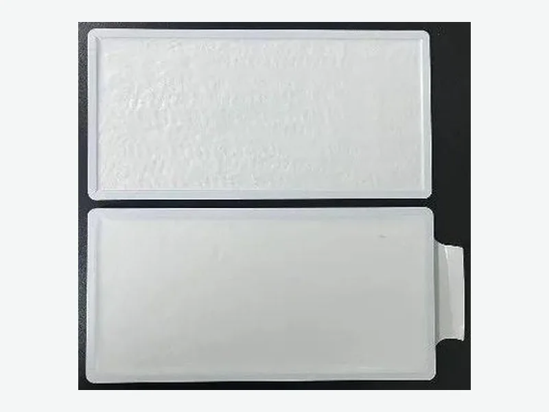
An LFP cell-to-cell thermal barrier specification starts with the module's mechanical and venting boundary conditions, not with a material datasheet. LFP cells have lower propagation risk than high-nickel chemistries, but the vent jet and compression path still drive barrier selection. Specify the cell format, gap, vent direction, compression load, and propagation acceptance first; then choose barrier material and thickness.
Why LFP Changes the Barrier Specification
LFP cells release less energy during thermal runaway than NMC or NCA cells, and propagation is slower and less certain. This does not remove the need for a cell-to-cell barrier; it changes the design target. The barrier must still interrupt the vent-jet path and maintain mechanical separation under compression, but the thermal exposure is shorter and less intense.
Recent industry coverage highlights tightening thermal-runaway safety mandates and growing LFP adoption, increasing the need for barrier specifications tailored to LFP's lower propagation risk but distinct vent-jet and compression behavior.1
- LFP propagation risk is lower but not zero; vent-jet and compression paths remain.
- Barrier specification must address transient jet impingement and sustained compression.
- Material selection should not be based on steady-state thermal conductivity alone.
Define the Cell Format and Gap First
Prismatic LFP cells have flat faces that allow a uniform barrier layer, but the cell-to-cell gap is often small, typically 1–3 mm. The barrier must fit within this gap without excessive compression set or edge overhang. Cylindrical LFP cells create a different geometry where the barrier may need to wrap or fill interstitial spaces.
For prismatic cells, a converted aerogel barrier with a nominal thickness of 0.5–6.0 mm can be die-cut to match the cell face. The compressed thickness under module assembly load must be confirmed, because aerogel compression changes thermal resistance and mechanical stress on the cell.2
- Measure the actual gap between cells under worst-case stack-up tolerance.
- Specify barrier nominal thickness and allowable compressed thickness.
- Consider edge clearance to avoid interference with cell tabs or vent features.
Vent Direction and Jet Impingement
LFP cells typically vent from the top or from a designated rupture area. The barrier must not block the vent path, but it must protect the adjacent cell from the hot gas jet. A barrier that covers the full cell face may redirect the jet or create a secondary path along the module wall.
During the thermal runaway process, the pressure relief vents at the top of batteries generate an intense axial high-pressure jet. The gas flow typically carries a large amount of heat and particles. The barrier design must account for this jet direction and velocity.3
- Identify the vent location and jet direction for the specific LFP cell.
- Specify barrier coverage relative to the vent opening.
- Consider a separate vent shield or deflector if the barrier cannot withstand direct jet impingement.
Compression Load and Mechanical Stability
Prismatic LFP modules often apply a compression load to maintain cell contact and manage swelling. The barrier must withstand this load without excessive creep or thickness loss. Aerogel barriers are compressible and can accommodate some swelling, but the compression set and stress relaxation must be characterized.
Aerogel thermal barriers are available in thicknesses from 0.50 to 6.00 mm with density from 70 to 200 kg/m³. These are representative screening ranges; the exact grade and construction must be confirmed per order. The barrier's mechanical behavior under the module's compression load must be validated in the customer's assembly.2
- Specify the module compression load and allowable barrier thickness change.
- Select a barrier with adequate compressive strength and low creep.
- Validate barrier thickness after cycling and after thermal exposure.
Material Selection: Aerogel vs. Mica Composite
Aerogel barriers offer very low thermal conductivity (0.012–0.030 W/m·K) and are thin, making them suitable for tight gaps. Mica composites provide higher rigidity and dielectric strength but are thicker and less compressible. For LFP modules, aerogel is often preferred for cell-to-cell spacing, while mica may be used as a module-level partition or vent shield.2, 4
A thermal model of cylindrical and prismatic lithium-ion cells suggests that a thermal barrier corresponding to roughly 0.4 mm of an aerogel-type layer or 4.3 mm of a mica-type layer may be needed for equivalent thermal resistance. This illustrates the thickness trade-off between material families.5
- Aerogel: thin, compressible, low thermal conductivity; verify compression set.
- Mica composite: rigid, high dielectric strength, thicker; verify edge quality and binder.
- Hybrid constructions may combine aerogel with a thin mica or polymer facing for handling.
Validation Protocol for LFP Barriers
A cell-to-cell barrier cannot be validated by material datasheet alone. The customer must run a propagation test on a representative module with the actual LFP cells, state of charge, and compression. The test should measure cold-side temperature, propagation time, and any vent-jet bypass.
To better suppress battery thermal runaway propagation, it is recommended to use thermal barriers with higher density and specific heat capacity. However, this must be balanced against thickness and weight constraints in the module.6
- Define the propagation acceptance criterion: no propagation, delayed propagation, or limited cell count.
- Test at worst-case state of charge and ambient temperature.
- Measure cold-side temperature and vent-jet path during the test.
- Validate barrier integrity after the test, including compression set and edge damage.
Drawing Inputs for a Converted Barrier
A drawing-specific converted barrier requires precise inputs: cell face dimensions, corner radii, tab locations, vent opening, and any adhesive or carrier requirements. The drawing should also specify the barrier's compressed thickness, edge finish, and any required markings for traceability.
VOLTFEND can slit, laminate, die cut, laser cut, inspect, and pack drawing-specific converted components. Samples are available within 7 days after drawing, material, and requirements confirmation, with no MOQ in principle. Special material availability is confirmed before commitment.2
- Provide a 2D drawing with all critical dimensions and tolerances.
- Specify material grade, thickness, and any adhesive or carrier.
- Include edge quality requirements and any marking or traceability needs.
- Confirm the compressed thickness target under module load.
PROJECT CHECKLIST
Inputs to bring into the next review
- 01Cell format (prismatic, cylindrical, pouch) and dimensions
- 02Cell chemistry and state of charge for worst-case propagation test
- 03Cell-to-cell gap and stack-up tolerance
- 04Vent location and jet direction
- 05Module compression load and allowable barrier thickness change
- 06Propagation acceptance criterion (no propagation, delayed, limited cell count)
- 07Barrier material family and thickness (aerogel, mica, hybrid)
- 08Drawing with dimensions, tolerances, edge quality, and traceability
- 09Validation plan including propagation test and post-test inspection
- 10Volume and delivery target for quotation
ENGINEERING FAQ
Questions teams commonly ask
Does an LFP module need a cell-to-cell thermal barrier at all?
Yes, because LFP cells can still undergo thermal runaway and propagate under certain conditions. The barrier addresses vent-jet and compression paths even when propagation risk is lower than high-nickel chemistries.
What is the typical thickness of an aerogel cell-to-cell barrier for LFP?
Aerogel barriers are available from 0.50 to 6.00 mm nominal thickness. The required thickness depends on the cell gap, compression load, and thermal resistance target. A thermal model may suggest an aerogel layer of roughly 0.4 mm for equivalent resistance to a much thicker mica layer.2, 5
Can a mica composite be used as a cell-to-cell barrier for LFP?
Yes, but mica composites are thicker and less compressible than aerogel. They may be better suited as module-level partitions or vent shields. The choice depends on the gap, compression, and dielectric requirements.4
How do I validate a cell-to-cell barrier for LFP propagation?
Run a propagation test on a representative module with actual LFP cells at worst-case state of charge and ambient temperature. Measure cold-side temperature, propagation time, and vent-jet bypass. The barrier must be validated in the complete assembly, not as a loose component.
What drawing information does VOLTFEND need to quote a converted barrier?
Provide a 2D drawing with cell face dimensions, corner radii, tab locations, vent opening, material grade, thickness, adhesive or carrier, edge quality, and traceability requirements. Also specify the compressed thickness target under module load.2
SOURCES
Evidence used in this brief
- 1Heat Shield Coatings For EV Battery Trays Market To 2035: Safety Mandates Drive Growth - News and Statistics
IndexBox · Accessed October 26, 2026
- 2Cell-to-Cell Aerogel Thermal Barriers engineering data and screening boundaries
VOLTFEND Engineering · Accessed October 26, 2026
- 3Checking your browser - reCAPTCHA
pmc.ncbi.nlm.nih.gov · Accessed October 26, 2026
- 4Mica & Composite Thermal Barriers engineering data and screening boundaries
VOLTFEND Engineering · Accessed October 26, 2026
- 5Thermal Model of Cylindrical and Prismatic Lithium-Ion Cells
researchgate.net · Accessed October 26, 2026
- 6Thermal barrier for preventing battery thermal runaway ...
sciencedirect.com · Accessed October 26, 2026