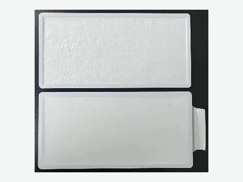
A useful cell-to-cell thermal barrier validation plan starts with the event and required module outcome, not a material data sheet. Define the initiating cell, state of charge, trigger, gap, restraint, vent direction and allowable neighboring-cell response. Then use three evidence gates: converted-part screening, installed-stack verification and representative module propagation testing. A barrier may delay heat transfer or protect selected surfaces, but no loose component can by itself prevent thermal runaway. The released decision belongs to the complete cell, barrier, restraint, busbar, cooling and enclosure configuration under its defined exposure.
1. Define the claim at the correct test level
Write one bounded claim before selecting a construction. For the specified initiating-cell condition, the target might be no adjacent-cell thermal runaway during the observation window. If propagation cannot be excluded, define a minimum delay and protected-side temperature limit. State whether the evidence covers a material comparison, installed cell stack, module or larger ESS safety case; these are not interchangeable claims.
UL Solutions separates UL 9540A evaluation into cell, module and larger system levels. Cell-level work addresses thermal-runaway characteristics and released gases; module-level work examines propagation tendency, heat and gas release, and ignition or deflagration potential. This hierarchy also helps bound internal engineering tests. A converted barrier is an input to module behavior, not a stand-alone UL 9540A-certified product.1
- Claim boundary: material, converted part, assembled stack, module, unit or site
- Outcome: no adjacent-cell runaway, minimum propagation delay, or a defined thermal-response limit
- Observation window and post-event inspection criteria
2. Characterize the initiating cell and exposure envelope
Freeze the conditions that control event severity: cell format, chemistry, capacity, conditioning, state of charge, orientation and trigger location. Record how the trigger differs from a credible field failure. Map cell-can contact, radiant heating, conduction through tabs or structure, hot-particle impact and vented-gas paths. A vent jet that bypasses the barrier edge makes a favorable through-thickness coupon result unrepresentative of the installed failure path.
Sandia's multi-cell pouch study shows why propagation must be tied to stack energy and thermal architecture. The researchers examined reduced state of charge and metal interlayers, related propagation limits to stored energy density, and used delays between cell events to study heat transfer. Do not transfer those results directly to another chemistry or geometry; test the actual state of charge, inter-cell contact and heat-capacity conditions.3
- Cell identity, lot, capacity, chemistry, conditioning and state of charge
- Trigger method, location, input energy and trigger-cell orientation
- Nominal and tolerance-limit gap, applied compression and restraint stiffness
- Vent outlet, edge bypasses, busbar paths and cooling plate contacts
3. Convert the hazard map into barrier requirements
Treat the barrier as a set of functions, not one thermal-conductivity number. It may need to reduce transient heat flow, remain positioned as cells expand, resist hot-gas erosion, preserve electrical isolation after deformation and avoid blocking a vent. Thickness, density, facings, adhesive, edge geometry and compression can alter these functions. Rank each against the exposure and distinguish safety-critical functions from packaging needs.
The safety case also needs controls beyond the inter-cell part. Sandia's grid-scale hazard analysis identified unsafe control actions and loss scenarios, then converted them into design objectives intended to reduce thermal-event likelihood or severity. Apply that logic locally: for each heat, gas, electrical and mechanical path, name the preventive control, mitigation, required evidence and consequence if the control is absent.2
- Through-face heating | screen transient thermal response | verify protected-cell response in the installed stack
- Edge or seam bypass | inspect coverage and assembly tolerance | instrument the exposed edge during the module event
- Vent-jet impingement | evaluate erosion, displacement and gas routing | confirm the representative vent path
- Compression or cell growth | measure thickness and force behavior after conditioning | verify that the barrier remains located
4. Use three evidence gates before release
Gate one is material and converted-part screening. Compare exact stack-ups at specified thickness, compression, temperature and exposure duration. Measure responses tied to the failure map, such as transient cold-side temperature, dimensional change, edge integrity and post-exposure electrical condition. Use the results to eliminate weak constructions and understand sensitivities, not as proof of module non-propagation.
Gate two is installed-stack verification. Assemble representative cells or thermal surrogates with production-intent gap, restraint, barrier outline, facings and adhesive orientation. Apply the expected pressure and a justified tolerance corner; instrument faces, edges and structural bypasses. Find integration failures such as curling, incomplete coverage, adhesive degradation, local crushing or heat flow around the barrier before consuming propagation-test hardware.
Gate three is a representative module propagation test using the defined cell and trigger. Record cell voltages, temperatures, event timing, venting, relevant pressure and post-test damage. UL Solutions identifies propagation tendency, heat and gas release, and ignition or deflagration potential as module-level UL 9540A concerns. Agree the formal plan and edition with the responsible test body; development tests do not replace required system evidence.1
- Gate 1 output: ranked constructions and documented material-level limitations
- Gate 2 output: verified assembly window and identified bypass paths
- Gate 3 output: pass or fail against the predefined module outcome, with event chronology
5. Build a test matrix that exposes sensitivities
Use a controlled baseline and change one primary factor at a time during screening. Cover construction, installed-thickness limits, compression, cell gap, vent orientation and relevant conditioning. Include an unprotected or current-production reference when it can be tested safely. Set the repeat strategy from expected cell variability; one favorable event is not a robust design margin.
Separate acceptance limits from diagnostics. Acceptance might concern adjacent-cell runaway, delay or a protected-surface limit. Diagnostics include time from initiating-cell vent to neighbor response, face and edge temperatures, barrier displacement, gas bypass and restraint deformation. Sandia used gap-crossing and cell-crossing time to describe propagation in its pouch-cell stacks. Similar definitions can aid comparison if set before testing without transferring Sandia's numeric results.3
- Factor matrix: construction, thickness, compression, gap, cell condition, orientation and conditioning
- Acceptance channels: neighboring-cell state, delay and protected-side thermal limits
- Diagnostic channels: face and edge temperature, voltage, event timing, pressure and visible vent path
6. Freeze the validated construction and change controls
The released drawing should identify material grade or controlled specification, thickness, outline, critical edge coverage, cutouts, facing and adhesive orientation, liner or pull-tab needs, assembly direction and inspection points. Link specimens to material lot, conversion route, drawing revision, cell lot and assembly record. Photograph the as-built stack so failures can be separated into material, conversion, fitment and system causes.
Define changes requiring review or revalidation: cell chemistry or supplier, state-of-charge window, gap, restraint, vent direction, barrier thickness, facing, adhesive, cutout or adjacent structure. Ask whether the change alters stored energy, heat capacity, contact resistance, gas routing or the safety-control structure. Sandia's propagation research and hazard analysis support treating those interactions as configuration-dependent.2, 3
- Release only the tested or technically justified construction window
- Keep sample genealogy and test configuration with the validation report
- Route cell, barrier, stack-up and vent-path changes through documented impact review
- Repeat the appropriate evidence gate when a change can affect the failure path
PROJECT CHECKLIST
Inputs to bring into the next review
- 01Cell format, chemistry, supplier and rated capacity
- 02Planned state of charge, cell conditioning, age and lot controls
- 03Module drawing, cell layout and complete inter-cell stack-up
- 04Nominal cell-to-cell gap and tolerance extremes
- 05Beginning- and end-of-life compression or restraint window
- 06Vent location, vent direction and nearby gas-flow or edge-bypass paths
- 07Trigger method, event orientation and required observation window
- 08Acceptance target for propagation, delay and protected-side temperature
- 09Environmental conditioning, voltage-isolation needs and post-test inspections
- 10Prototype quantity, expected production volume and required traceability records
ENGINEERING FAQ
Questions teams commonly ask
Can a coupon test prove that a cell-to-cell barrier stops propagation?
No. A coupon test can rank exact stack-ups under a defined heat exposure and reveal sensitivity to thickness, compression or edge condition. It does not reproduce the initiating cell, vent jet, structural bypasses, restraint or neighboring-cell response. Use it as Gate 1, then verify the installed stack and representative module against the stated outcome.
Is a cell-to-cell barrier UL 9540A certified?
Do not describe a loose barrier that way. UL Solutions presents UL 9540A with cell, module and larger system levels; module testing addresses propagation tendency and heat, gas, ignition and deflagration hazards. A barrier can be one controlled element, but the evidence and claim belong to the tested system boundary.1
Which variables should be worst-cased in a propagation test?
Start with variables that can increase event energy or reduce margin: cell condition and state of charge, gap, barrier thickness tolerance, compression, vent direction, edge coverage and structural heat paths. The worst combination is design-specific, so use screening and hazard analysis to justify the test corner.2, 3
When should a barrier or module change trigger revalidation?
Review changes that can alter stored energy, heat capacity, thermal contact, barrier position, vent routing, electrical isolation or the initiating-cell scenario. Assign the lowest evidence gate that resolves the risk, while retaining module retesting for changes that can affect propagation. Record the rationale even when testing is not repeated.
SOURCES
Evidence used in this brief
- 1UL 9540A Test Method for Battery Energy Storage Systems (BESS)
UL Solutions · Accessed October 2, 2026
- 2Grid-scale Energy Storage Hazard Analysis & Design Objectives for System Safety
Sandia National Laboratories · Published August 1, 2020 · Accessed October 2, 2026
- 3Passive Mitigation of Cascading Propagation in Multi-Cell Lithium Ion Batteries
Sandia National Laboratories · Published January 7, 2020 · Accessed October 2, 2026