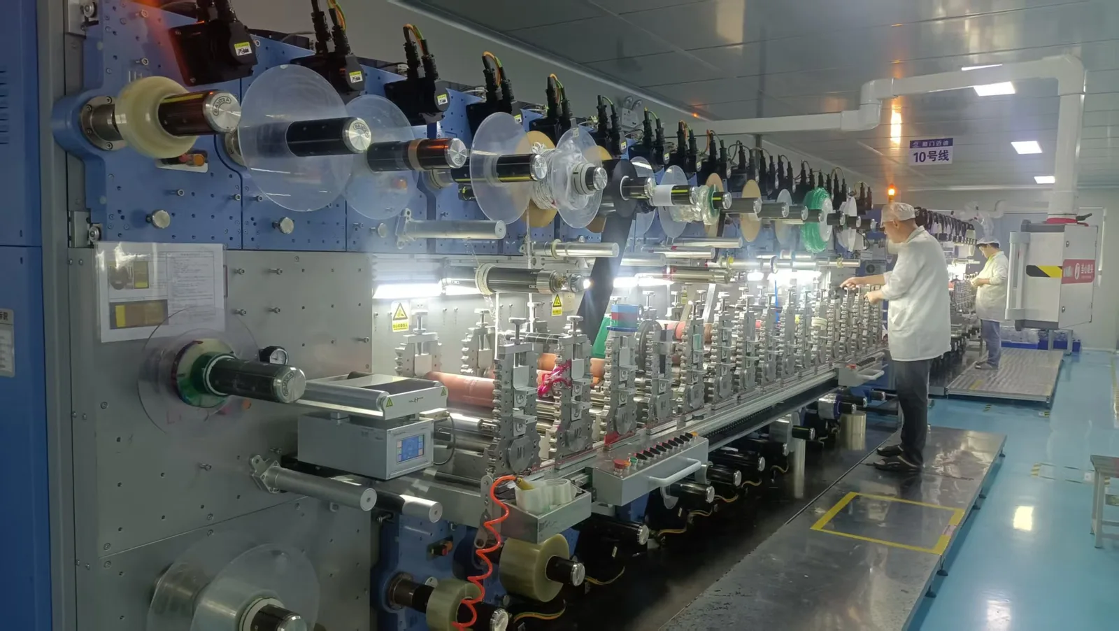
Battery insulation components are die-cut from soft, compressible, or layered materials. Their tolerances cannot be copied from metal machining practice. The right specification starts with the functional interface: what the part must touch, seal, insulate, or allow to pass. From there, material behavior and assembly method set the realistic tolerance window.
Start with the functional interface, not the part outline
A die-cut insulation part has several possible functional interfaces: a cell face, a busbar, a cooling plate, a compression pad, a housing wall, or a vent path. Each interface has a different tolerance need. A part that only needs to cover a cell face can have a loose outline tolerance if the material is compliant and the adhesive or compression holds it in place. A part that must align with a busbar opening or a vent slot needs a tighter positional tolerance because misalignment can create a short-circuit path or block gas flow.
Before assigning numbers, list every interface the part touches and classify it as critical, functional, or cosmetic. Critical interfaces affect safety or high-voltage isolation. Functional interfaces affect assembly or thermal performance. Cosmetic interfaces have no measurable effect. This classification prevents over-tolerancing the entire part because one small feature is critical.
- Critical: busbar clearance, vent opening alignment, high-voltage creepage path
- Functional: cell face coverage, compression pad registration, adhesive bond area
- Cosmetic: edge straightness on a captured part, liner overhang outside the bond area
Material dimensional stability sets the floor
Battery insulation materials include aerogel blankets, mica sheets, ceramic papers, silicone foams, polyimide films, and multi-layer laminates. Each family has a different response to temperature, humidity, and tension during converting. Aerogel blankets can compress permanently under pressure. Mica can crack if bent too sharply. Silicone foam can relax after die cutting. Polyimide film is dimensionally stable but can tear if the die is dull.
Dimensional stability after heat exposure is a key parameter for insulation sheets. A material that shrinks or expands after thermal cycling will not hold the same tolerance as a stable film. The supplier data sheet may give a value at room temperature, but the part must be measured after the same conditioning the battery will see. If the material changes dimension by 0.5% after a thermal cycle, a 100 mm part can move 0.5 mm. That movement must be included in the tolerance stack.1
Some thermal barrier materials are designed to maintain thickness under high compression. For example, one supplier reports that a low-compression barrier thins by less than 5% under conditions where a conventional aerogel compresses by as much as 60%. This difference changes the tolerance approach. A material that holds thickness can be specified with a tighter thickness tolerance because the installed thickness is predictable. A material that compresses significantly needs a tolerance on the compressed thickness, not the free-state thickness.2
- Measure free-state thickness and compressed thickness separately
- Include thermal and humidity conditioning before dimensional inspection
- Ask for dimensional stability data at the maximum service temperature, not just room temperature
Tolerance stack-up in the module
A battery module is a stack of cells, compression pads, insulation sheets, and end plates. Each layer has a thickness tolerance. The total stack height tolerance is the root-sum-square or worst-case sum of the individual tolerances, depending on the assembly method. If the insulation part is 1.0 mm ±0.1 mm and the compression pad is 2.0 mm ±0.2 mm, the combined stack can vary by more than the individual parts. The insulation part must either absorb that variation through compliance or be specified with a tighter tolerance than the stack allows.
Compression pads are often used to compensate for manufacturing and assembly tolerances. A compliant pad can take up stack variation without transferring excessive force to the cells. If the insulation part is rigid, it cannot do this. The tolerance on the insulation part must then be tight enough to keep the total stack within the cell manufacturer's allowed compression range. This is a design decision, not a supplier decision.3
A practical approach is to build a tolerance stack-up table for the module. List every layer, its nominal thickness, its tolerance, and its compression behavior. Then calculate the worst-case and statistical stack height. Compare that to the cell manufacturer's allowed compression range. If the stack is outside the range, either tighten a tolerance or add a compliant layer. The insulation part is often the easiest layer to adjust because it can be made from a compressible material.
- List every layer in the stack with nominal thickness and tolerance
- Calculate worst-case and statistical stack height
- Compare to cell manufacturer's allowed compression range
- Adjust insulation part tolerance or material compliance to close the gap
Die-cutting process capability and cost drivers
Rotary die cutting, flatbed die cutting, and laser cutting have different tolerance capabilities. Rotary die cutting is fast and consistent for high volumes but requires a cylindrical die and is less flexible for design changes. Flatbed die cutting is more flexible and can handle thicker materials but may have slightly lower positional accuracy. Laser cutting can produce very tight tolerances and complex shapes but is slower and can leave heat-affected edges on some materials.
Tolerance is a cost driver. A ±0.5 mm outline tolerance on a soft foam part is inexpensive. A ±0.1 mm tolerance on the same part may require a different cutting method, more frequent die maintenance, and higher scrap. The cost increase is not linear. Before tightening a tolerance, ask what functional requirement demands it. If the answer is 'it looks better' or 'we always do that', the tolerance is probably too tight.
A converter can often hold tighter tolerances on certain features than on others. A hole position can be held tighter than the outer outline because the hole is cut with the same die stroke. A slot width can be held tighter than the slot length because the width is controlled by the die blade, while the length is controlled by the material feed. Specify critical features separately from non-critical features.
- Rotary die cutting: high volume, consistent, moderate tolerance
- Flatbed die cutting: flexible, thicker materials, slightly lower positional accuracy
- Laser cutting: tight tolerance, complex shapes, slower, possible edge effects
- Specify critical features separately from the part outline
Drawing inputs that prevent tolerance surprises
A drawing that only shows the part outline and a general tolerance block is not enough for a battery insulation component. The drawing should identify the functional interfaces, the material stack-up, the adhesive areas, the liner requirements, and the critical dimensions. It should also state the measurement method and the conditioning before inspection. A part measured at 23°C and 50% RH may be different from the same part measured after a thermal cycle.
For multi-layer laminates, the drawing should show the layer order and the adhesive type. A tolerance on the total thickness is not the same as a tolerance on each layer. If the adhesive layer is 0.05 mm and the insulation layer is 1.0 mm, the total thickness tolerance must account for both. The drawing should also state whether the part is supplied on a liner, in a roll, or as individual pieces. Liner release force and pull-tab requirements affect assembly speed and should be specified.
A useful drawing review checks these items: material grade and thickness for each layer, adhesive type and coverage, critical dimensions with tolerances, datum scheme, measurement method, conditioning, liner and packaging, and any special requirements like cleanliness or traceability. A converter can review the drawing and flag tolerance conflicts before tooling is made.
- Identify functional interfaces and critical dimensions
- Show layer stack-up and adhesive coverage
- State measurement method and conditioning
- Specify liner, packaging, and traceability requirements
Validation protocol for tolerance release
Before releasing a tolerance specification, validate it with a first article inspection and a small assembly trial. The first article should measure every dimension on the drawing using the same method the production inspector will use. The assembly trial should place the part in the actual module stack and check for interference, gaps, and compression force. If the part fits in the trial but fails the drawing tolerance, the drawing tolerance is wrong, not the part.
A validation matrix can be built with these columns: dimension, tolerance, measurement method, sample size, acceptance criteria, and result. For critical dimensions, use a larger sample size and a tighter acceptance criterion. For non-critical dimensions, a smaller sample is acceptable. The matrix should be reviewed and signed by both the design engineer and the quality engineer.
After the first article is approved, lock the material grade, adhesive, liner, and cutting method. Any change to these inputs requires a new first article. This is standard change control practice and prevents tolerance drift when a supplier changes a material lot or a cutting die.
- First article inspection with the production measurement method
- Assembly trial in the actual module stack
- Validation matrix with sample size and acceptance criteria
- Change control for material, adhesive, liner, and cutting method
Decision matrix: when to tighten a tolerance
Use this decision matrix to decide whether a tolerance should be tightened. For each dimension, ask four questions: Is the interface critical for safety or high-voltage isolation? Does the material have low dimensional stability? Is the part rigid or captured in a stack? Does the assembly process have no compliance? If the answer to two or more questions is yes, the tolerance likely needs to be tight. If the answer to all four is no, the tolerance can be loose.
Example: a busbar clearance slot on a rigid mica sheet. The interface is critical for high-voltage isolation. Mica has moderate dimensional stability. The part is rigid. The assembly process has no compliance. All four answers are yes, so the slot position tolerance should be tight, perhaps ±0.2 mm or better. Example: a cell face cover on a compressible aerogel blanket. The interface is functional, not critical. Aerogel has low dimensional stability. The part is compressible. The assembly process has compliance from the compression pad. All four answers are no, so the outline tolerance can be loose, perhaps ±1.0 mm.
- Critical interface: yes/no
- Low material dimensional stability: yes/no
- Rigid or captured part: yes/no
- No assembly compliance: yes/no
- Two or more yes answers: tighten tolerance
PROJECT CHECKLIST
Inputs to bring into the next review
- 01Cell format, chemistry, and state of charge range
- 02Drawing with layer stack-up, adhesive areas, and critical dimensions
- 03Functional interface list with critical/functional/cosmetic classification
- 04Material grade and thickness for each layer
- 05Tolerance stack-up table for the module
- 06Cell manufacturer's allowed compression range
- 07Measurement method and conditioning before inspection
- 08Liner, packaging, and traceability requirements
- 09Validation target: first article, assembly trial, or production lot
- 10Volume and delivery schedule for quotation
ENGINEERING FAQ
Questions teams commonly ask
What is a typical die-cut tolerance for a soft battery insulation part?
For a compressible foam or aerogel blanket, an outline tolerance of ±0.5 mm to ±1.0 mm is often achievable without significant cost. Tighter tolerances are possible but require a stable material and a controlled cutting process. The functional interface should drive the number, not a general tolerance block.
How does material dimensional stability affect die-cut tolerance?
Materials that shrink or expand with temperature or humidity will not hold the same tolerance as stable films. A material with 0.5% dimensional change can move 0.5 mm on a 100 mm part. The tolerance must include this movement, or the part must be conditioned before measurement.1
Should I specify tolerance on free-state or compressed thickness?
For compressible insulation parts, specify tolerance on the compressed thickness at the expected assembly pressure. Free-state thickness is useful for incoming inspection but does not represent the installed condition. A material that compresses 60% under load needs a different tolerance approach than one that compresses less than 5%.2
How do I decide between rotary die cutting and laser cutting for tight tolerances?
Rotary die cutting is best for high volumes with moderate tolerances. Laser cutting can hold tighter tolerances and complex shapes but is slower and may leave heat-affected edges. Flatbed die cutting is a flexible middle ground. The choice depends on volume, material, and the specific tolerance required.
What drawing information does a converter need to quote a tolerance?
The converter needs the material grade and thickness for each layer, the adhesive type and coverage, the critical dimensions with tolerances, the datum scheme, the measurement method, and any conditioning requirements. Liner, packaging, and traceability requirements should also be stated. A drawing review can flag tolerance conflicts before tooling is made.
SOURCES
Evidence used in this brief
- 1Lithium Battery Thermal Insulation Sheet Selection Guide | Key Parameters and Material Comparison
firebirdref.com · Accessed October 14, 2026
- 2Uncompromising high-performance thermal protection in battery energy storage systems with GORE battery insulation technology | E Source
esource.com · Published November 18, 2025 · Accessed October 14, 2026
- 3EV Battery Compression Pad Requirements and Selection ...
linkedin.com · Accessed October 14, 2026